Let's see I have my final exams for my physiology course this week, along with looking up information sessions for nursing schools. Suffice to say I have barely enough time to work on this. Man I shouldn't even be writing this, but oh well. Okay first off I'll describe the modification I did to the shoulders. This gives it some additional mobility by allowing the shoulder axis to go move vertically upward as well as swing out horizontally. The effect of this increases the arm movement which is important for mimicking human body motion. I still haven't figured out a good pose yet, though the display stand I made for it somewhat limits my choices.
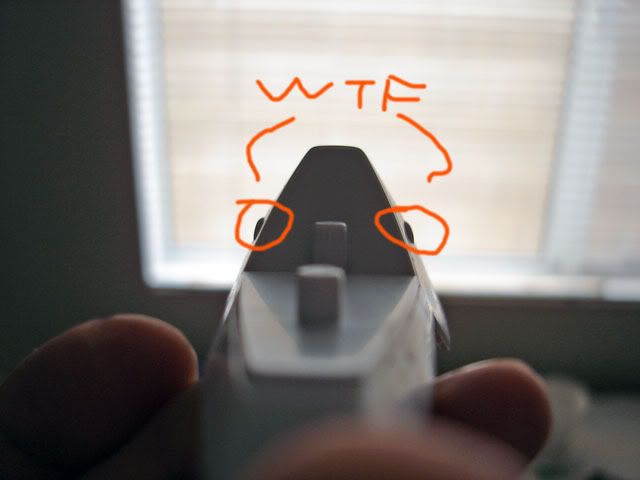
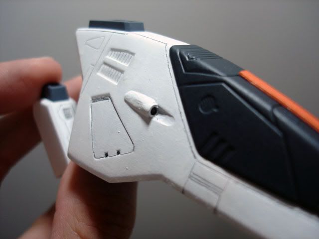
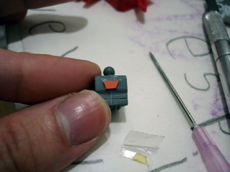
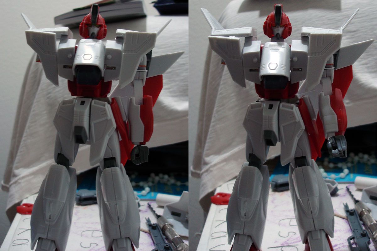
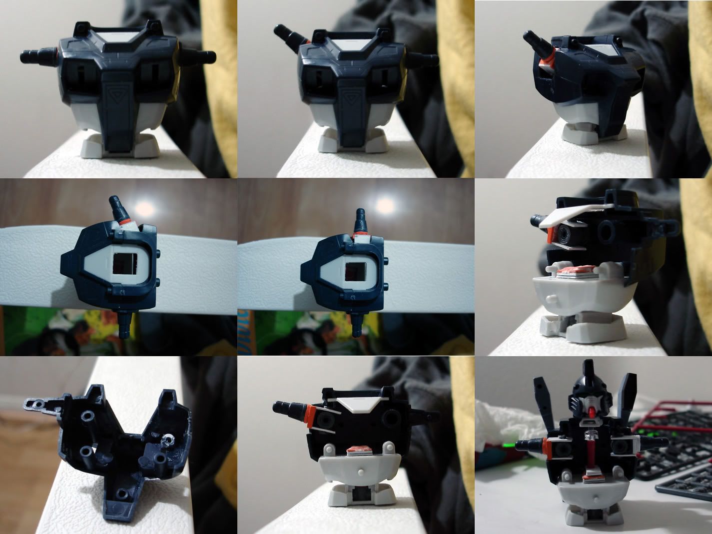
The two halves of the upper torso are held in place by your normal peg assembly, and also by the connection to the abdomen, which is a separate assembly (white). I noticed that the large male pegs that keep the torso together also double as a rotational point for the ever plentiful PC A (sometimes PC C) polycap. So I chopped it off, along with a sizeable amount of the female end and super glued that in place. Then I took your average credit card and enclosed the polycap. Polycap goes on the peg, and voila, a two-axis joint.
I'm not certain I'll be making another update before AX.
Saturday, June 26, 2010
Monday, June 14, 2010
Sunday, June 13, 2010
Friday, June 11, 2010
I've added my twitter feed on the side. I'll be using it to make tiny updates every now and then. Right now I'm using it to upload pictures of my Deathscythe WIP, which I'm hopefully going to finish by Anime Expo to enter the BAKUC 2010 contest.
Monday, February 22, 2010
HG ACROSS THE UNIVERSE
Bandai has announced a new HG line that will merge the existing HGUC line with designs from other Gundam continuities. HG ZZ Gundam and HG Gundam X will be the first of this new line that will feature G, W, X, and Turn A designs in addition to other UC designs.
HG GUNDAM X-APRIL
HG GUNDAM ZZ-JUNE
GLORIOUS. Below is image.

HG GUNDAM X-APRIL
HG GUNDAM ZZ-JUNE
GLORIOUS. Below is image.

Saturday, January 02, 2010
Saturday, July 18, 2009
Monday, June 29, 2009
ALMOST THERRRRRRRRRR

WHAT THE HELLLLLLLLLLLLLLL
The guns on the side of the plane "cockpit" are only HALF molded. Picture half a cylinder.
Fine, well SCREW YOU BANDAI :P I'LL JUST MAKE MY OWN GUNDAMN VULCANS
Wing is done!
CRAP A SEAM OPENED UP NOOOOOOOOOOOOO I HAVE NO TIME TO FIX IT.
I have 2 days until Anime Expo, and a lab practicum on Wed. Must keep going with the other shit because there is no time left, and I NEED MY A ON THIS EXAM :wacko:
Oh and new picture. Oh crap, need to dull coat the head.
Monday, June 22, 2009
Starting painting
Friday, May 15, 2009
Zeta C1 Type

Click for bigger picture, and more pictures at below link:
http://www.bakuc.com/modeler/derringer/4638
Friday, April 10, 2009
Idea Ho Ho!
Thursday, March 12, 2009
Hobby Japan Shananigans 1
Not much time to work on Airmaster at the moment because of school. Here are some things I did recently. A lot of kits have certain areas that will eventually be covered by other parts, like the shoulder guards. This makes it extremely difficult to paint. So the solution is a Hobby Japan technique that's featured in almost every tip they use.


As you can see, there is a "C" on the piece on the left side. The male peg can now slide into that space from the side. Here's another picture for the wings. The red portion of the wings can now be painted separately and inserted into the 2 halves.


Here's a schematic showcasing this. Normally the wings are composed of 3 parts. The red portion is sandwiched in the middle between 2 white pieces. Using the C joint mod, the white part can be assembled first, and the red portion can simply be inserted in. This allows SUPER easy painting without masking.
Friday, February 13, 2009
Hands
Quick update today!
So the hands are composed of 2 halves with some interesting molding detail on them. Uh...okay, if I fix that seam those details will disappear. Hmmmah what will I do?
So! I'll get rid of ALL the detail and rescribe it!
So the hands are composed of 2 halves with some interesting molding detail on them. Uh...okay, if I fix that seam those details will disappear. Hmmmah what will I do?
So! I'll get rid of ALL the detail and rescribe it!
Friday, February 06, 2009
Time?
So how do you people manage to have time for building things if you have school? I've barely managed to get additional work done on the Airmaster let alone the other stuff I sort of opened to fiddle with.
Saturday, January 24, 2009
Arms!!!!! part 2
Comparison of my first arm on the left, and the new arm on the right. The joint was originally too long and gave a rather weird appearance. Right side also shows how much better the guy looks with a longer neck.
Here are some additional pictures of the arm
Now I just have to add details to the joint. CycloneX suggests I use the semi-circular sprues, so I'll have to see how that goes. I will also have to prime this to see how off the axis is.
I also now have a schematic in case anyone wants to replicate this:
The holes use a 7/64 size drill bit and are the right size to use plastic sprue.
Speaking of which. The quality of this Airmaster is pretty bad. There were a lot of instances of flash on the parts trees and it looks like various panel lines are not as deep as they should be.
Tuesday, January 20, 2009
Urghhh MCB 160L
Monday, January 19, 2009
Arms!!!!! part 1
Ha, no updates for a week because I've been busy perfecting my joint substitution trick. Photo below is the prototype I first came up with. It was a little on the thin side, but had a large range of movement compared to the original polycap arm. New one looks slightly different from this.
Essentially, my arm joint consists of credit card plastic, with the shiny stuff/magnetic bar sanded off. A shell is constructed, while the cavity is filled with epoxy putty. 2 sets of holes are made to allow a rod to pass through. The top uses the kit's own molded rod, while the bottom is simply inserted


The rod is a sprue from the plastic tree the parts were cut from. I'm using one of the ABS plastic trees from another kit, since I don't trust this kit's plastic. More on this later...
Subscribe to:
Posts (Atom)